
I'm gonna go ahead and say it: I'm a Whovian. Ever since I was introduced to it, my inner geek couldn't get enough of the Daleks, Cybermen, and the Time Lords. I imagined how awesome it would be to have the powers of a Time Lord - a TARDIS of my own in which to travel through time, a companion to accompany me on all of my adventures, a Sonic Screwdriver with all the bells and whistles...
Wait a minute! I may not be able to get my hands on a TARDIS, and it might be a bit much to make someone follow me around sidekick style, but a Sonic Screwdriver is definitely engineer-able! So, as the result of many hours of labor, I am now the proud owner of a (somewhat functional) Sonic Screwdriver! And to give it my own flair, I have christened it The RevEngineer's Sonic Screwdriver!
And if you're a Time-Lord-hopeful like me, and you want a Sonic Screwdriver of your very own, then you're in luck; I'll show you how I came up with the concept and design of my screwdriver, and even guide you through how I built it! So enough dilly-dally, let's get this road on the show! Allons-y!
Contents
Concept

|
In my opinion, the circuit was too simple; as haooken says in his video, "yes, you could turn it on with a regular flashlight." As soon as I built the circuit and wired it in, I had to turn off all of the lights in my room, because even the ambient light was enough to activate the phototransistor! My shadow was the only thing keeping the computer off; as soon as I stepped away from it, it turned on! Now, this was mostly because the resistor I coupled with the transistor was making it super sensitive, but if I reduced the sensitivity, the effective range would also take a hit. I solved this problem at first by hiding the sensor deep within the shadows of the computer case, and immediately regretted doing so. The sensor was so buried and obscured that the screwdriver would only turn it on when at the perfect angle with respect to the sensor. To make matters worse, I nearly broke the contraption (and my computer) trying to get it out. Things were getting complicated fast, and that's usually when I take a step back and revisit the basics. All I wanted was to be able to turn this thing on from across the room... just like a TV remote. And that is exactly where I got the inspiration for the next phase of the project.
Back to top.
Design

|

|
I also decided to use the handy 555 to build a circuit that would flash the visible blue LED in the Screwdriver at a variable rate, that could be adjusted using a trimmer pot accessible on the outside of the Screwdriver. The circuit was simply placed before the blue LED, after the Screwdriver's main circuit board.
David Cook goes into some detail about the operation and uses of 555 timers, but there is a great resource that I frequently went to for help, called The Electronics Club. More specifically, their page on 555 timers helped me get an understanding of the general operation of 555s and how to design a circuit around one. I recommend you check both these pages out if you want to brush up on your knowledge of these versatile ICs.
Back to top.
Preparation
After the research is done, and a working schematic is put together, I had to buy all the necessary parts to construct the circuit. The first place I looked at was a longtime trusted vendor, Jameco Electronics; they sell lots of electronic parts, as well as tools, testing equipment, and entire kits for all kinds of projects. Jameco's headquarters is in Belmont, CA, so for those of you located in the Bay Area, ordering your parts on a Monday generally means that you'll see them on your front porch on Tuesday. I like that. However, they don't always have everything I need, especially when it comes to more specialized parts, so for those I usually go to either Mouser Electronics or Newark/element14.
According to my design, the total parts list comes down to this (every part is one of each, unless specified) -
For the IR Circuit:
- 3.9 kOhm Resistor
- 39 kOhm Resistor
- 4.7 kOhm Resistor
- 0.47 uF Ceramic Capacitor
- PN2222BU NPN Transistor
- LM555CN Timer IC
- Wide angle IR (940 nm) LED
- Long range IR (940 nm) LED
For the receiver circuit:
- 100 Ohm Resistor
- 0.47 uF Ceramic Capacitor
- TSOP1238 38kHz IR Receiver
For the blue flasher circuit:
- 470 Ohm Resistor
- 47 uF Ceramic Capacitor
- 47 kOhm Trimmer Resistor
- LM555CN Timer IC
- Blue (468 nm) LED
I also needed to buy smaller, more compact button cells to replace the default ones in the Screwdriver with. The ones that are supplied are LR1154 (SR44) type, which supply 1.5v each. The new circuits require approximately an extra 1.5v to operate, so my solution was to double up one of the three battery slots with two LR1121 (SR55) types, which also supply 1.5v and are about half the thickness of the others.
Back to top.
Construction
The first thing I needed to do was what I'm best at: taking things apart. I began dismantling the Sonic Screwdriver, very methodically, so as not to break anything. The first step was to remove the shaft from the outer shell; all that required was loosening one screw. Then I (very carefully) used an Xacto knife to split the seam where the head was glued together. I also had to remove the blue lens, which took a little more brain power and brute strength to figure out. At this point, I had the Screwdriver completely open, and was staring at the inner workings, ready to begin.

All the internals of the Screwdriver.
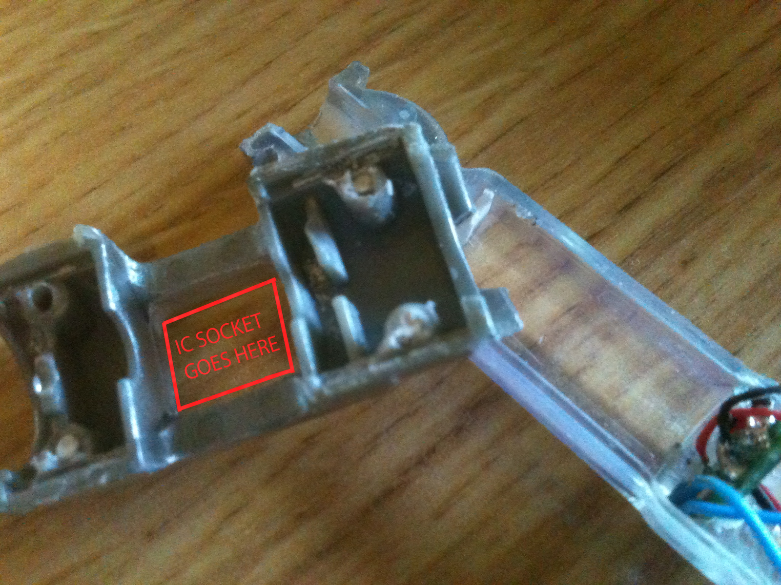
To make more room on the inside, I had to cut away a lot of the inner structure, this time with a hot knife attachment for my soldering iron (this made removing everything a whole lot easier). I took mostly everything out, including the seat where the speaker was, as well as the shaft that sat inside the head, just below the lens. This freed up enough space for all of the components, save the ICs, which I mounted on the outside of the head by placing them in super-glued-into-place IC mounts.
It's bigger on the inside...
Now that all the wibbly-wobbly, timey-wimey... stuff... was removed, all that was left to do was assemble the circuits inside the screwdriver; I made each circuit on opposite sides of the head, by soldering each component to the IC mounts that I super glued on the outside. The IR LEDs were attached to the transmitter side of the head, while the single blue LED was attached on the other side. Once the heads were put together, the LEDs sat in a triangular orientation.

I still don't know how it all fit.
Since the LEDs occupied more space than the singe LED that came with the Screwdriver, I had to redesign the lens for the LEDs. After digging through some spare junk that I had sitting around, I built an extension for the blue lens to sit on out of some old flashlight parts and superglued it to the head.
The circuits were wired in parallel to each other, and the supply voltage was taken from the LED output on the original circuit that came with the Screwdriver. Ground is ground. At this point, all that was left to do was reassemble the body and add some "decorations," for which I just superglued some more "junk" to the outside.
And that is that! My very own Sonic (*cough* IR *cough*) Screwdriver was now complete; all I had left to do was construct the receiver circuit, which I explain in the next section.
Back to top.
Receiver Circuit
The receiver circuit is decidedly less complex than the transmitter, as it only involves a few components and the special receiver unit. The receiver unit acts like a gate that is designed to only activate if it detects a light signal modulating at 38kHz, give or take a certain amount. The circuit would have a signal output, which would be the same level as the supply voltage, and a ground. When the receiver detects a signal from the Screwdriver, the circuit will close, activating whatever the circuit is attached to. Couldn't get any simpler.

Schematic for the receiver circuit. Note that in this configuration, the "Out" pin on the receiver is actually a return, with the "In" pin wired to the positive end of whatever the circuit is attached to.

The receiver circuit on the breadboard.
Back to top.
So that's that; I hope you learned a lot, and possibly even feel inspired to try it out for yourself! If you need any help, or just have something to say about the project, feel free to email me directly, or leave a comment below. I like comments! Comments are cool!
THIS IS SO COOL!!!!!!!!!!!!
ReplyDelete